Nissan Rogue Service Manual: B terminal circuit
Description
Terminal “B” is constantly supplied with battery power.
Diagnosis Procedure
Regarding Wiring Diagram information, refer to STR-7, "Wiring Diagram".
CAUTION: Perform diagnosis under the condition that the engine cannot start by the following procedure.
- Remove fuel pump fuse.
- Crank or start the engine (where possible) until the fuel pressure is released.
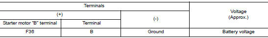
1.CHECK “B” TERMINAL CIRCUIT
- Turn ignition switch OFF.
- Check that starter motor ”B” terminal connection is clean and tight.
- Check voltage between starter motor ”B” terminal and ground.
Is the inspection result normal? YES >> GO TO 2.
NO >> Check harness between battery and starter motor for open circuit.
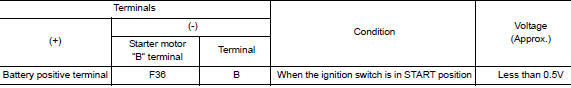
2.CHECK BATTERY CABLE CONNECTION STATUS (VOLTAGE DROP TEST)
- Shift selector lever to ”P” (Park) or ”N” (Neutral) position.
- Check voltage between battery positive terminal and starter motor ”B” terminal.
Is the inspection result normal? YES >> GO TO 3.
NO >> Check harness between the battery and starter motor for continuity.
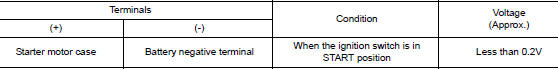
3.CHECK GROUND CIRCUIT STATUS (VOLTAGE DROP TEST)
- Shift selector lever to ”P” (Park) or ”N” (Neutral) position.
- Check voltage between starter motor case and battery negative terminal.
Is the inspection result normal?
YES >> “B” terminal circuit is OK. Further inspection is necessary. Refer to STR-11, "Work Flow (With GR8-1200 NI)" or STR-15, "Work Flow (Without GR8-1200 NI)".
NO >> Check the starter motor case to engine mounting for high resistance.

 S connector circuit
Description
The starter motor magnetic switch is supplied with power when the ignition
switch is turned to the START position
while the selector lever is in the P (Park) or N (Neutral) position.
...
Other materials:
Diagnosis system (BCM)
WITH INTELLIGENT KEY
WITH INTELLIGENT KEY : CONSULT Function (BCM - COMMON ITEM)
APPLICATION ITEM
CONSULT performs the following functions via CAN communication with BCM.
Direct Diagnostic Mode
Description
Ecu Identification
The BCM part number is displayed.
Self D ...
LATCH (Lower Anchors and Tethers for CHildren) System
LATCH system lower anchor locations - bench seat
Your vehicle is equipped with special anchor
points that are used with LATCH system compatible
child restraints. This system may also be
referred to as the ISOFIX or ISOFIX compatible
system. With this system, you do not have to use
a vehicl ...
P0031, P0032 A/F sensor 1 heater
DTC Description
DTC DETECTION LOGIC
DTC No.
CONSULT screen terms
(Trouble diagnosis content)
DTC detecting condition
P0031
A/F SEN1 HTR (B1)
[Air fuel ratio (A/F) sensor 1 heater (bank
1)control circuit low]
The current amperage in the A/F sensor 1 heater circu ...