Nissan Rogue Service Manual: DTC/circuit diagnosis
SPORT MODE SWITCH
Component Function Check
1. CHECK SPORT MODE SWITCH OPERATION
- Turn ignition switch ON.
- Check SPORT mode indicator lamp turns ON/OFF on combination meter when turn SPORT mode switch ON/OFF.
Is the inspection result normal? YES >> INSPECTION END
NO >> Proceed to DMS-13, "Diagnosis Procedure".
Diagnosis Procedure
1.CHECK SPORT MODE SWITCH CIRCUIT
- Turn ignition switch OFF.
- Disconnect SPORT mode switch harness connector.
- Turn ignition switch ON.
- Check voltage between SPORT mode switch harness connector terminals.
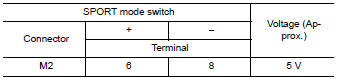
Is the inspection result normal? YES >> GO TO 6.
NO >> GO TO 2.
2.CHECK GROUND CIRCUIT
- Turn ignition switch OFF.
- Check the continuity between SPORT mode switch harness connector and ground.
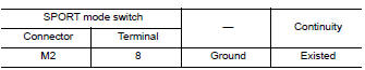
Is the inspection result normal? YES >> GO TO 3.
NO >> Repair or replace damaged parts.
3.CHECK CIRCUIT BETWEEN COMBINATION METER AND SPORT MODE SWITCH (1)
- Disconnect combination meter harness connector M76.
- Check continuity between combination meter harness connector terminal and SPORT mode switch harness connector terminal.
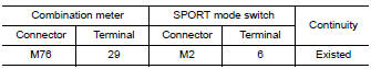
Is the inspection result normal? YES >> GO TO 4.
NO >> Repair or replace damaged parts.
4.CHECK CIRCUIT BETWEEN COMBINATION METER AND SPORT MODE SWITCH (2)
Check continuity between combination meter harness connector terminal and SPORT mode switch harness connector terminal.
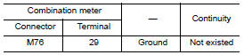
Is the inspection result normal? YES >> GO TO 5.
NO >> Repair or replace damaged parts.
5.CHECK COMBINATION METER INPUT/OUTPUT SIGNAL
- Connect all of disconnected connectors.
- Check input/output signal of combination meter. Refer to MWI-24, "Reference Value".
Is the inspection result normal? YES >> Check intermittent incident. Refer to GI-41, "Intermittent Incident".
NO >> Replace combination meter. Refer to MWI-82, "Removal and Installation".
6.CHECK SPORT MODE SWITCH
Check SPORT mode switch. Refer to DMS-14, "Component Inspection".
Is the inspection result normal? YES >> Check intermittent incident. Refer to GI-41, "Intermittent Incident".
NO >> Replace SPORT mode switch. Refer to DMS-16, "Removal and Installation".
Component Inspection
1.CHECK SPORT MODE SWITCH
Check continuity between SPORT mode switch connector terminals.
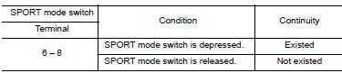
Is the inspection result normal? YES >> INSPECTION END
NO >> Replace SPORT mode switch. Refer to DMS-16, "Removal and Installation".
 Basic inspection
DIAGNOSIS AND REPAIR WORK FLOW
Work Flow
DETAILED FLOW
1.OBTAIN INFORMATION ABOUT SYMPTOM
Interview the customer to obtain as much information as possible about the
conditions and environment un ...
 Symptom diagnosis
THE SPORT MODE INDICATOR LAMP DOES NOT TURN ON
Description
The SPORT mode indicator lamp does not turn ON when the SPORT mode switch is
operated.
Diagnosis Procedure
1.CHECK SPORT MODE INDICATOR ...
Other materials:
System description
COMPONENT PARTS
Component Parts Location
View under rear of front passenger
seat
View with spare tire cover removed
Center of back door
View with glove box removed
No.
Component
Function
1
Rod antenna
Refer to AV-232, &quo ...
Oil seal
VALVE OIL SEAL
VALVE OIL SEAL : Removal and Installation
REMOVAL
Remove camshafts. Refer to EM-64, "Removal and Installation".
Remove valve lifters. Refer to EM-56, "Disassembly and Assembly".
Rotate crankshaft, and set piston whose valve oil seal is t ...
U1050, U1051 LIN communication
DTC Description
DTC DETECTION LOGIC
DTC No.
CONSULT screen terms
(Trouble diagnosis content)
DTC detecting condition
U1050
LIN COMMUNICATION
[LIN (Local Interconnect Network) communication)]
ECM detects LIN communication error.
U1051
POSSIBLE CAUSE
...