Nissan Rogue Service Manual: Valve timing control
Exploded View
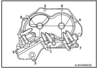
- Valve timing cover
- 2. O-rings
- Intake valve timing intermediate lock control solenoid valve
- Intake valve timing control solenoid valve
- Exhaust valve timing control solenoid valve
Intake Valve Timing Intermediate Lock Control Solenoid Valve, Intake Valve Timing Control Solenoid Valve, and Exhaust Valve Timing Control Solenoid Valve
REMOVAL
- Disconnect the battery negative terminal. Refer to PG-75, "Exploded View"
- Remove cowl top extension. Refer to EXT-25, "Removal and Installation".
- Remove the RH engine mount torque rod. Refer to EM-81, "Exploded View".
- Use a suitable jack (A) to securely support the bottom of the engine (1) and the transaxle assembly (2).
CAUTION: Put a piece of wood or an equivalent as the supporting surface and secure in a stable condition.

- Remove A/C line bracket bolt.
- Remove harness grounds from engine mounting bracket (RH).
- Remove harness retainers from engine mounting bracket (RH).
- Remove the engine mounting bracket (RH). Refer to EM-81, "Exploded View"
- Remove the RH engine mounting support bracket. Refer to EM-81, "Exploded View".
- Remove the RH engine mount torque rod. Refer to EM-81, "Exploded View".
- Disconnect harness connectors from intake valve timing intermediate lock control solenoid valve, intake valve timing control solenoid valve, and exhaust valve timing control solenoid valve connectors.
- Remove intake valve timing intermediate lock control solenoid valve, intake valve timing control solenoid valve, and exhaust valve timing control solenoid valve bolts.
- Remove intake valve timing intermediate lock control solenoid valve, intake valve timing control solenoid valve, exhaust valve timing control solenoid valve from valve timing control cover.
- . Remove O-rings from intake valve timing intermediate lock control solenoid valve, intake valve timing control solenoid valve, and exhaust valve timing control solenoid valve.
INSTALLATION
Installation is in the reverse order of removal.
CAUTION:
- Do not reuse O-rings.
- Lubricate O-rings with clean engine oil before installing.
Valve Timing Control Cover
REMOVAL
- Remove the intake valve timing intermediate lock control solenoid valve, intake valve timing control solenoid valve, exhaust valve timing control solenoid valve. Refer to EM-74, "Intake Valve Timing Intermediate Lock Control Solenoid Valve, Intake Valve Timing Control Solenoid Valve, and Exhaust Valve Timing Control Solenoid Valve".
- Remove harness grounds and retainers from the top if the engine mount bracket.
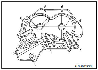
- Loosen the valve timing control cover bolts in the reverse order shown.
- Remove the valve timing control cover bolts.
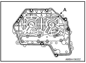
- Remove the valve timing control cover by cutting the liquid gasket using Tool (A).
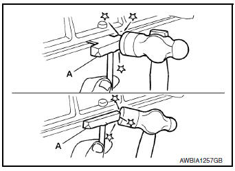
Tool number : KV10111100 (J-37228)
NOTE: Do not loosen screws (A) on the back of the valve timing control cover.
INSTALLATION
- Install valve timing control cover with the following procedure.
- Install intake valve timing intermediate lock control solenoid valve, intake valve timing control solenoid valve and exhaust valve timing control solenoid valve to valve timing control cover.
- Install O-ring to front cover side.
CAUTION: Do not reuse O-ring.
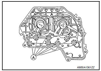
- Apply liquid gasket to the positions shown. Refer to GI-22, "Recommended Chemical Products and Sealants".
Diameter (A) : 3.4 - 4.4 mm (0.134 - 0.173 in)
- Install valve timing control cover.
- Tighten the bolts to specification in the numerical order shown.
 Camshaft
Exploded View
Camshaft position sensor (INT)
O-ring
Camshaft brackets (INT)
Camshaft brackets (EXH)
Camshaft (INT)
O-ring
Camshaft bracket (No. 1)
Camshaft sproc ...
 Oil seal
VALVE OIL SEAL
VALVE OIL SEAL : Removal and Installation
REMOVAL
Remove camshafts. Refer to EM-64, "Removal and Installation".
Remove valve lifters. Refer to EM-56, " ...
Other materials:
Hill start assist system
Hill start assist system
WARNING
Never rely solely on the hill start assist
system to prevent the vehicle from moving
backward on a hill. Always drive
carefully and attentively. Depress the
brake pedal when the vehicle is stopped
on a steep hill. Be especial ...
Diagnosis system (EPS control unit)
CONSULT Function
FUNCTION
CONSULT can display each diagnostic item using the diagnostic test modes
shown following
Diagnostic test mode
Function
ECU identification
The part number stored in the control unit can be read.
Self diagnostic result
Self-diagnosti ...
System
System Description
The system switches fluid pressure of each brake caliper to increase, to
hold or to decrease according to
signals from control unit in ABS actuator and electric unit (control unit).
This control system is applied to
VDC function, TCS function, ABS function, EBD funct ...